Welcome to South Africa's Audio Visual community!

Welcome to the home for South African audio and visual equipment owners and enthusiasts. Whether you are an audiophile or a hobbyist, feel welcome to join us in the exciting discussions about amplifiers, turntables, receivers, speakers, projectors, screens, restoration and new projects, product reviews, accessories, classifieds, and so much more!

  • The image upload funtion has been upgraded! Enjoy!

Restoration Quad 303 restoration

Restoration projects
If this is a thriller @Family_Dog then you need to see some of the investigations I have done! I actually love this and am learning so much!

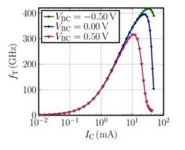
I spent some time on Research Gate and found this interesting graph showing the transition frequency fT of a Bipolar transistor. It shows that the applied voltage has almost no influence. Now I have no idea if this trend can be applied in general to all bipolar transistors?
1714810290599.png
 
Some more interesting information on fT. The following contains in a post by Vikram Sekar.

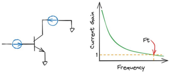
Ft is an important metric for the AC response of a transistor. Here's a quick low down on it.

Let's assume you have a transistor (like a BJT). You feed it with a little AC current at the input, short the output terminal, and measure the output AC current.

This is called current gain.

As you increase the AC current frequency, the capacitance at the input terminal shunts more and more current away from the transistor.

At a high enough frequency, the transistor cannot amplify AC current any more. This frequency is called "Transit Frequency" represented by Ft.

If you can build a transistor with a very low input capacitance, it would shunt away lesser AC current and therefore have a higher Ft.

If that is not possible, you have to find ways to improve the magnitude of current gain to improve Ft (like improve mobility).

To measure Ft, you can convert S-parameters to H-parameters, and extrapolate H21 (=I2/I1) to unity current gain. The frequency where H21=1 gives you Ft.

The amount of time taken by a signal to go from input to output is inversely proportional to Ft. Higher the Ft, lesser the time, faster your circuit.

This is why Ft remains such a key metric for transistor manufacturers.

1714810964842.png


Also of interest is a reply by Gary M. Moore which reads as follows:

... In my day, it was called unity gain.
I did it this way. I would take a transistor gain stage, and bias it at Class A.
then, I would adjust the collector resistance, such that, it would drop exactly half the supply voltage across the transistor. This gives us the static impedance of the device. Then, to calculate what the gain would be at unity, is when the R of the transistor equals the value of the Xc of the device at some given frequency. When these two values match, meaning the capacitance of the transistor is shunting the frequency to ground ; equal to the base-emitter Xc, the gain is equal to 1.
 
Onto the Regulator board.

TR200

This transistor was a SGS U17229, the service manual then replaced it with ZTX504. Subsequently this was replaced by a BC556B.

Towers lists four different versions, the only difference being the lead info. Whatever that may be!

TR200.jpg


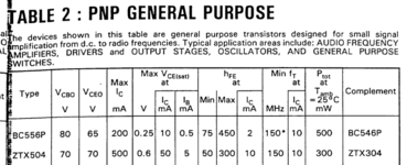
An old Farnell specification sheet lists the ZTX504 as having the following characteristics

1715029007868.png


From an old post of mine the following characteristics:

RatingZTX504BC556B
Collector - Emitter Voltage-70 VDC-65 VDC
Collector - Base Voltage-70 VDC-80 VDC
Emitter - Base Voltage-5.0 VDC-5.0 VDC
 
The last two evenings were spent double checking my work on the TR100 to TR106 and compiling a summary table.

This is the best I can come up with for the vintage versions of these transistors.


Quad 303 - Transistors TR100-TR106.jpg
 
Back
Top