Welcome to South Africa's Audio Visual community!

Welcome to the home for South African audio and visual equipment owners and enthusiasts. Whether you are an audiophile or a hobbyist, feel welcome to join us in the exciting discussions about amplifiers, turntables, receivers, speakers, projectors, screens, restoration and new projects, product reviews, accessories, classifieds, and so much more!

  • The image upload funtion has been upgraded! Enjoy!

Custom Wolverine Slow Build

DIY and custom designed projects

kolakidd

Active member
Joined
Aug 27, 2023
Messages
73
Location
Johannesburg
This is going to be a cross-post slow build. Life is unpredictable and doesn’t allow a whole weekend of building anymore.

This build is dedicated to Mike. When I first told him I would be doing it and my reasoning, I got raised eyebrows, and I don’t think he bought my need for another amp. I will have his voice in my head and ensure every wire is equal in length ;)

The Build.
So what is different about this build, and why am I doing it?
  1. I will be using SMPS supplies*. Yup… you read that right. I am building a mono-block configuration with MicroAudio SMPS supplies. Sami has been super helpful in getting around the chip shortage and rustling me up a set. The choice of SMPS is based on efficiency and recent experiences in other projects. I feel like we have hit a point where a quality SMPS can compete with linear, and actually… energy efficiency… it’s a thing. Yes… I still have a bunch of amps that double up as excellent heaters in winter, so I am not about to go fundamentalist at any point. The enclosure design will also accommodate a linear switch if needed.
  2. Linear AF. I don’t want a completely linear system. I know the sound I like, but getting to that sound with every component contributing to its sound is difficult. My idea here is to build a system that is as linear as possible, where the significant contribution (I guess colouration) comes from the preamplifier. Why the preamplifier? I have many of them; they are easier and cheaper to build than speakers and amplifiers. I almost went class-d*and waited for Purifi’s new offering, but ultimately, I couldn’t. For me, DIY has to be more than just plugging boards into each other. The Wolverine, with good quality parts and matching transistors, matches the low distortion and linearity of class-d.
Truth be told, for low distortion linearity, I already have a set of Vanguards, but they’re in a system that sounds so good that I don’t want to mess with it. The Vanguard is still one of the best amps I have had in my system.

So here we go… Post 1.
A box of parts from Mouser, RS, and Mantech and a board from Canada.
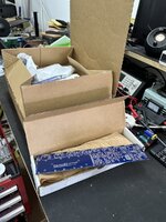
IMG_1713.jpg
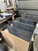
A pile of bent 2mm steel
(I’ll share the design when I am done; for now, you can try to figure it out.)
IMG_1715.jpg

Next steps
  • The chassis went to powder coating today.
  • The build will commence soon.
  • SMPSs are in customs
  • Having some milling work done on heatsinks.

Addendum: Please don’t request updates. I don’t have much time, so I will be doing it between things.
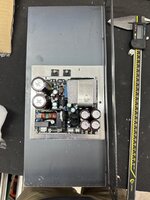
 
Microaudio SMPs arrived all the way from Jordan. Honestly, Jordan is a first for shipping origin for me, but Sami does make good PSUs. The quailty and parts are all of the highest standard.
Aramex and customs made these a super fun experience.

These are the SMPS600 frame, but with modifications. Unfortunately the global chip shortage meant that Sami had to modify these to get me to where I needed to be to the SMPS630-G spec. There are two, one per Mono Block.

The bracket it is lying on is part of the Amp mounting and shielding idea I have.


IMG_1736.jpg
 
I was watching a repair channel to learn more about how and why amplifiers fail. The biggest problem the chap find are the cluster of four caps exactly as seen in your new PSU. The caps overheat as there is limited airflow between them.

I would suggest you add some airflow channel to those four tower caps to keep them cool.
 
You are correct. Without giving away the chassis design, that is a bracket that is currently lying on it’s side it will be vertically mounted, the large rectangular gap in the base of the bracket will align with vents on the top and bottom of the chassis to get a lot of airflow.
 
This was some work from last weekend.

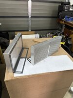
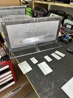
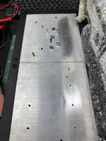
Tapping heatsinks and fitting heatsinks to installation brackets. Then making PCB mounted heatsinks.

All I can say is thank the lord for spiral flute taps. What a pleasure for blind tapping.

IMG_1741.jpg
IMG_1742.jpg
 
Have you electrically isolated the aluminium from the steel frame? You have three materials there. The stainless steel screws will oxidize the aluminium and the steel will also do so.

Use aluminium screws/bolts and isolate from the steel frame is what I would recommend from experience.
 
Yes, I've used Thread Locker for that purpose.

I'm not too worried about the metal frame, as that will be treated when I do the final mounting
 
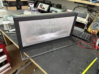
Again, some weekend work. I did a quick dry fit of the powder-coated chassis; it's looking surprisingly good.

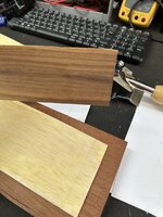
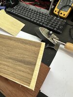
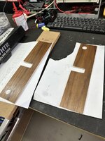
I didn't have much time outside of Sunday Afternoon, which I spent working on part of the face. Thought I might document that because it is a technique I have used to replace wooden amp faces before, and all those repairs are still around.

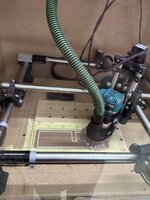
Spoiler alert, I have an MPCNC, but I used to cut these by hand with a scalpel.

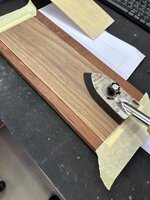
My method is laminate on balsa using the iron on method for lamination.

So, obviously apply glue to both the balsa and laminate and allow to dry completely

IMG_1756.jpeg

Heat up with an iron.
IMG_1757.jpeg


Fully Bonded piece

IMG_1758.jpeg
Into the CNC. I use 32,000RP and shallow 0.2mm cuts. The laminate and glue stop tear-out


IMG_1761.jpg

Final piece. This is about 3mm thick, which I need for this design, but I have done a 1mm piece, although, that is scalpel work.IMG_1763.jpg


I have some time off this week, and it's time I did the boards.
 
Well done so far! I've been a bit busy and missed the entire thread, thoroughly enjoyed reading through it now.
 
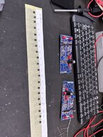
I had a little time and started the boards.

I realised I haven't actually posted anything about the Wolverine for those who haven't followed the Diyaudio thread, here are the details:
https://www.diyaudio.com/community/threads/diy-class-a-b-amp-the-wolverine-build-thread.385920/


Anyway, the big thing about achieving ultra-low distortion in this amp is transistor matching. You get very low distortion with mismatched transistors, but if you're OCD and you want the full value then it's matching on your plate.

So, matching was made a heck of a lot easier with AI. I used Gemini to find ideal matches, which worked really well.

IMG_1774.jpeg

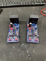
These are the near complete IPS boards, awaiting the final heatsinks

IMG_1776.jpeg
 
Next up was some work on the chassis.

Really a case of measure twice (times 100 in Autodesk) mount once.

IMG_1779.jpeg

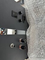
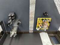
For the back, I found an interesting speaker protect on Audiophonics, which I ended up modifying slightly.

IMG_1778.jpeg

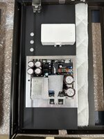
Then onto mounting the PSUs on their brackets. I also mounted a Sonoff POW, more on that in a sec.

IMG_1777.jpeg
So the POW Origin is an interesting beast. It gives me a Wifi Switch, which is now part of all of my builds, makes remote and timed turn on a synch. What the new POW origin also gives you is programmable over and under voltage protection.

There is also a bunch of measurement data, but that isn't important right now.

Luckily the POW Origin is easier than the original POW to wire an external switch into.

IMG_1784.jpg

Oh, and finally just spray sealed the Heatsink brackets.
IMG_1780.jpeg
 
And so it grows...


I started to read about the Wolverine in the link you provided but 3805 posts will take me forever to finish. I'll do it the easy way and follow your progress reports here! :)

-F_D
 
The biggest problem with 3,805 posts is sifting through opinions and arguments.

The actual build guide, though, is incredibly well-documented. I have never seen anything like it. The difference, though, with this build is the rigour in component selection and matching components. The BOM is quite bulky with all of that.
 
...slow build...

Apart from not having much time, I am waiting for some matched transistor pairs to arrive from various parts of the world.

In the meantime, I decided to change the orientation of the boards on the heatsinks. I have switched my method for mounting heatsinks. More than once, I have had the screw part of standoffs break in their hole. I now use a combination of grub screws and female-to-female standoffs. It works very well.

IMG_1814.png

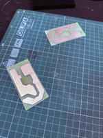
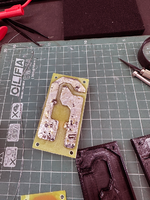
I found a nice PCB on PCBWay for the Rod Elliot ground lift. However, it was like $35 for five small boards, and it is the kind of board I can do on my CNC. I have tried making complex boards on the CNC, and it is possible; I am never 100% certain about the results, especially with HV. In this case, the spacing can be vast between tracks, so it is easier to clean out any traces left behind by the bit.

Here's the result:

IMG_1808.png

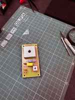
For extra safety I printed out cases, and then mount them with silicone and screws
IMG_1813.png

Populated
IMG_1812.png

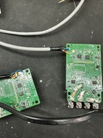
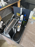
This weekend, I had a little time and started wiring in the Power Supply section of the Amp. You'll start to get an idea of the design. The extra length of grey cables are literally waiting to get cut down and connected. That length is just so that I have some cable to work with

IMG_1816.png
 

Attachments

  • IMG_1809.png
    IMG_1809.png
    2.1 MB · Views: 0
  • IMG_1811.png
    IMG_1811.png
    2.3 MB · Views: 0
Back
Top