Welcome to South Africa's Audio Visual community!
Welcome to the home for South African audio and visual equipment owners and enthusiasts. Whether you are an audiophile or a hobbyist, feel welcome to join us in the exciting discussions about amplifiers, turntables, receivers, speakers, projectors, screens, restoration and new projects, product reviews, accessories, classifieds, and so much more!
You are using an out of date browser. It may not display this or other websites correctly.
You should upgrade or use an alternative browser.
You should upgrade or use an alternative browser.
Custom Wolverine Slow Build
- Thread starter kolakidd
- Start date
DIY and custom designed projects
kolakidd
Active member
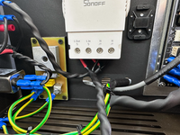
Thanks, I might do that. I generally follow the T-Ground schema.
Currently, the ground screw you see in the images isn't the signal ground point.
It's structured like this:
Signal Ground + 0V Line > Ground Lift > Chassis Ground
The earth wires going into the Chassis Ground point are
Mains Earth + Ground Lift
Power Cable Shields
Currently, the ground screw you see in the images isn't the signal ground point.
It's structured like this:
Signal Ground + 0V Line > Ground Lift > Chassis Ground
The earth wires going into the Chassis Ground point are
Mains Earth + Ground Lift
Power Cable Shields
kolakidd
Active member
Family_Dog
Administrator
Seems you are very well organised with your CNC and other equipment, very nice!
-F_D
-F_D
mygoggie
Administrator
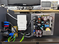
OK, yes, I was worried about ground looping and then a floating ground as a single bolt always have nasty way of undoing itself (breaker creep).So, the Ground lift board has two spades that replicate a T-Groud. Top is 0V, bottom is PCB Ground. The screw terminal is then connected to Chassis ground.
That's with 80% complete wiring. I still need to apply heat shrink to some cable and beaten things up a bit.
mygoggie
Administrator
BTW, your workbench is way too neat. Never trust a mechanic with a tidy workbench!
kolakidd
Active member
My workbench is chaos, I have two 3m workbenches, and neither has space right now!
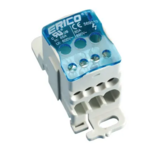
As you mentioned, I do like this terminal block. I found it on RS (I have used Nvent products before, and they are top-notch). I am going to buy a couple for future projects. It could be a better way to emulate a T-ground connection. I normally do a star washer connection at the chassis end with a riv-nut.
As you mentioned, I do like this terminal block. I found it on RS (I have used Nvent products before, and they are top-notch). I am going to buy a couple for future projects. It could be a better way to emulate a T-ground connection. I normally do a star washer connection at the chassis end with a riv-nut.
naboo
Well-known member
Looking good! As a matter of interest which cnc do you have? I built the 3d printed dremel cnc, works great but the dremel as a spindle I am struggling to keep stable. Thinking if I swop the dremel out I might have a much better product.
kolakidd
Active member
Thanks!
I built the MPCNC, and it runs on the Makita RT0700C.
The RT0700C is kind of the go-to router for DIY CNC if you aren't going for a standalone spindle. You'll find a lot of brackets for it.
The MPCNC requires a lot of 3D printing to build but is a pretty straightforward build. As others have succeeded, I tried it on aluminium, but it strains. I also built mine to handle larger pieces, so it's ideal on wood. It's pretty damn accurate if you make it carefully. Honestly, though, I think I am going to migrate to a fully metal CNC at some point, I've glanced at a couple of options.
I outsource all metal cutting and CNC work. A couple of years ago, I heard some wise advice from Paladin. The problem with CNC is that you must sit and watch the job because things can go spectacularly wrong. That part is a real pain in the A$$ with large jobs.
mygoggie
Administrator
True words spoken!I outsource all metal cutting and CNC work. A couple of years ago, I heard some wise advice from Paladin. The problem with CNC is that you must sit and watch the job because things can go spectacularly wrong. That part is a real pain in the A$$ with large jobs.


