Welcome to South Africa's Audio Visual community!
Welcome to the home for South African audio and visual equipment owners and enthusiasts. Whether you are an audiophile or a hobbyist, feel welcome to join us in the exciting discussions about amplifiers, turntables, receivers, speakers, projectors, screens, restoration and new projects, product reviews, accessories, classifieds, and so much more!
You are using an out of date browser. It may not display this or other websites correctly.
You should upgrade or use an alternative browser.
You should upgrade or use an alternative browser.
Repair Kenwood KRF-V4080D
- Thread starter mygoggie
- Start date
Repair and fixing of audio equipment
Family_Dog
Administrator
Quite likely in the final AF stage of the faulty channel. Check the DC bias offset before connecting to good speakers.
Are these the PCBs you cleaned with our mixture?
-F_D
Are these the PCBs you cleaned with our mixture?
-F_D
mygoggie
Administrator
Yeah it worked a charm once again!Quite likely in the final AF stage of the faulty channel. Check the DC bias offset before connecting to good speakers.
Are these the PCBs you cleaned with our mixture?
-F_D
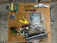
Look at all the crud that came off the boards. These were the last to be cleaned.
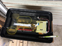
The issue is the main (bottom) PCB will only come alive if the CPU switches it on. For that I need to solder the ribbons back. If I need to replace a component on the PCB I need to desolder the ribbons to gain access. So, I need to find out how to manually get the relays to activate on the main PCB and work from there.
I have the repair manual, so best is to RTFM before I think too much.
Family_Dog
Administrator
IIRC, ribbon cable connectors have a type of clamping mechanism that clamps the ribbon cable into the connector, no soldering required. Are those different??
-F_D
-F_D
mygoggie
Administrator
IIRC, ribbon cable connectors have a type of clamping mechanism that clamps the ribbon cable into the connector, no soldering required. Are those different??
-F_D
Yes, the ribbon wires are directly soldered. I actuallly discussed this with our old equipment expert @Sarel.wagner before desoldering.
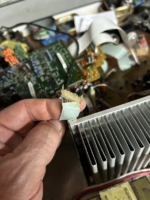
Family_Dog
Administrator
Crazy... offhand I cannot recall having ever seeing soldered multi-pin connectors like that.
-F_D
-F_D
mygoggie
Administrator
Yeah it is very weird. It also has tiny orange connectors that looks like plugs but also need to be desoldered. These are spring pins so it is not easy to desolder. Some foreign words did help!
So far I found a blown fuse, detached voltage regulator and a few dry joints.
Assembling now to check what is what.
So far I found a blown fuse, detached voltage regulator and a few dry joints.
Assembling now to check what is what.
Family_Dog
Administrator
Good luck with this, I think I would have been cringing with fear under my bed by now with that weird assembly. Most unusual for Kenwood.
-F_D
-F_D
mygoggie
Administrator
Man when will the invention of new words ever end? Soldering those ribbon wires back required some new words of encouragement!
No holy smoke appeared with switching it on. The LCD display flakes in and out of displaying so I need to hunt for a dry joint on that PCB as well.
Plays nicely on ear phones. Will advance to speakers tomorrow.
Radio circuit just renders white noise. Maybe the PCB for the radio section needs some love as well.
Tomorrow is another day!
mygoggie
Administrator
Haha, no need to rush so I took my time. Yeah very weird but then it is a video audio receiver amplifier. Too many things in a box IMHO.Good luck with this, I think I would have been cringing with fear under my bed by now with that weird assembly. Most unusual for Kenwood.
-F_D
Family_Dog
Administrator
Radio circuit just renders white noise. Maybe the PCB for the radio section needs some love as well.
Nah... just needs an antenna!
-F_D
mygoggie
Administrator
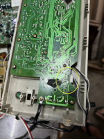
This morning I removed the display and control PCB to find the display fault. The power supply plug socket was at fault. It was loose from the solder pads. I resoldered most all the joints on the PCB as quite a few looked flaky and it was not that many to do.
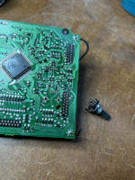
I also found that the volume knob did not really work correctly. So I desoldered it and cleaned it with @Family_Dog 's favourite drink. What a load of black soot came out of it! Someone must have been a heavy smoker where this amplifier lived as most of the interior was covered in smoke and nicotene deposits.
Reassembled all and there we are. Front panel working correctly with the LCD staying on, the volume knob functioning as it should and the push buttons showing a much better press feeling.
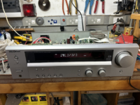
I let it play for an hour and then it went into standby mode ... sigh. The manual states that the flashing standby light means there is a speaker wire short.

Well it played for an hour with speakers connected ... so it can only be a speaker output transistor or capacitor that with heat changed into a shorting component. I will let it cool down, reset the microprocessor and see if that makes a difference.
I will have to find which component is the output transistor and see if I can find a replacement in any case.

I also found that the volume knob did not really work correctly. So I desoldered it and cleaned it with @Family_Dog 's favourite drink. What a load of black soot came out of it! Someone must have been a heavy smoker where this amplifier lived as most of the interior was covered in smoke and nicotene deposits.

Reassembled all and there we are. Front panel working correctly with the LCD staying on, the volume knob functioning as it should and the push buttons showing a much better press feeling.

I let it play for an hour and then it went into standby mode ... sigh. The manual states that the flashing standby light means there is a speaker wire short.

Well it played for an hour with speakers connected ... so it can only be a speaker output transistor or capacitor that with heat changed into a shorting component. I will let it cool down, reset the microprocessor and see if that makes a difference.
I will have to find which component is the output transistor and see if I can find a replacement in any case.
mygoggie
Administrator
Tried again, with a reset and the amp immediately goes into limp mode ...
One thing for Kenwood is they sometimes does do some engineering. The two channel voltage regulators are easy to access! It also comes with a readily available desoldering heatsink!
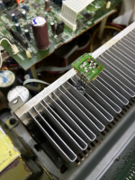
Both desoldered and the one with the red probe pointing accusingly at it is shorted on on side. The other one measures out of spec as well.
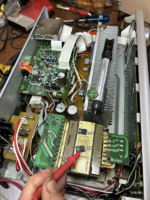
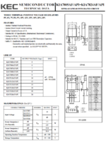
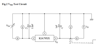
The broken one reads KIA 7812A and the other one KIA 7912PI ... now I wonder why the difference. Let me see what the manual says and also look at the spec sheets for these two cranky babies.
Then onto finding why these are damaged.
One thing for Kenwood is they sometimes does do some engineering. The two channel voltage regulators are easy to access! It also comes with a readily available desoldering heatsink!

Both desoldered and the one with the red probe pointing accusingly at it is shorted on on side. The other one measures out of spec as well.

The broken one reads KIA 7812A and the other one KIA 7912PI ... now I wonder why the difference. Let me see what the manual says and also look at the spec sheets for these two cranky babies.
Then onto finding why these are damaged.
Last edited:
mygoggie
Administrator
Attachments
mygoggie
Administrator
Both tested correctly. I soldered them back. Amp is working again and sound is a lot less tinny.
Will keep it playing until I notice something happening ...
Will keep it playing until I notice something happening ...
Sarel.wagner
Well-known member
Certain types of gear had lots of those at one time, things like Printers, TV's, Amps, Fax macines etc. I guess it shows my ageCrazy... offhand I cannot recall having ever seeing soldered multi-pin connectors like that.
-F_D
Groetnis
mygoggie
Administrator
And the playing lasted for 27 minutes and then the amplifier went into limp mode again.
This area of components were quite hot to the touch and it is also where the power transistors are to be found.
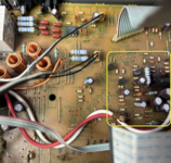
In the schematic diagram it is clear (to me that is ..) that this is the power amplification area.
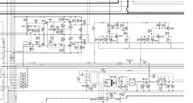
I will start measuring voltages of the lines feeding this area and then see if the problem lies upstream of or inside this area of ocmponents.
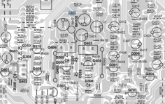
This area of components were quite hot to the touch and it is also where the power transistors are to be found.

In the schematic diagram it is clear (to me that is ..) that this is the power amplification area.

I will start measuring voltages of the lines feeding this area and then see if the problem lies upstream of or inside this area of ocmponents.

Family_Dog
Administrator
Have you checked the DC Off-set bias? From your pics, it appears that the PCB is severely burnt?
-F_D
-F_D
mygoggie
Administrator
@Family_Dog the values are as follows, measured directly at the speaker outlet terminals. Your wisdom will be appreciated.
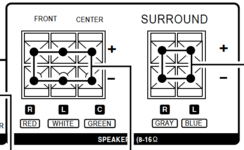
EDIT: Add values after 20 minutes of ON

Speaker | Measurement [mV DC] |
| |
| Front right | -33,6 | -33,0 | |
| Front left | -40,9 | -40,1 | |
| Front center | -19,85 | -19.2 | |
| Surround right | drops from 13,8 to 12,05 and keeps dropping | random between -25 to +6 | |
| Surround left | 15,5 | slowly fluctuates between +8 to + 16 |
EDIT: Add values after 20 minutes of ON
Last edited:
Family_Dog
Administrator
Those values should not cause problems, it is always better to keep to the absolute lowest possible. But you need to leave the amplifier on for 20 minutes minimum and then measure again and readjust if necessary, they can drift somewhat.
Does
Does
