Welcome to South Africa's Audio Visual community!

Welcome to the home for South African audio and visual equipment owners and enthusiasts. Whether you are an audiophile or a hobbyist, feel welcome to join us in the exciting discussions about amplifiers, turntables, receivers, speakers, projectors, screens, restoration and new projects, product reviews, accessories, classifieds, and so much more!

  • The image upload funtion has been upgraded! Enjoy!

Repair Kenwood KRF-V4080D

Repair and fixing of audio equipment
I did another round of measurements after 20 minutes of on. The amp does not stay on for longer. The new values are in the table above.

It seams the problem is in the surround circuit.
 
I took my time and identified all the components listed in the diagram on the PCB and then measured each component.

Interesting that most all the transistors measure with leakage and one is open circuit on the B-E side. Most all the 47k resistors have failed and measure any value less than the 47k. One diode is open circuit both ways and a few measure a forward bias potential of 1V. Did not measure the caps as I need to remove the PCB for this ... (another job).

So, yes something seriously went wrong here. I will need to figure out where to measure the circuit's bus feed potential's on the PCB and check if these are the +76V, -76V and -12V as specified.

test results.png
 
My logic tells me that something upstream is causing havoc in the amplification block of components.

I identified four places where I could solder wires onto components to allow me to measure the bus feed potentials.

Low and behold, the -74V bus supply measures -64,5V and the +76V measures +41,5V. I traced the circuit back for the +76V bus and it leads to a bridge rectifier number D121. From the bridge rectifier there is only one component downstream and that is capacitor C142. Further downstream is wire bridge W247 which leads to the location from where I measured previously.

I desoldered the wire bridge W247 and then measured the voltage again directly on the bridge rectifier. It starts off at 105V and then drops to 35V and then goes back up to 68V. So ... either the capacitor is FUBAR or the bridge rectifier is. I will desolder these tomorrow and check what the readings say.

1712600694772.png
 
The cap may have dried up and is not doing its thing, probably a good move to replace all the electrolytics in any case. I would also replace the bridge rectifiers, they are cheap enough.

In one of my Vintage threads I had similar problems with a Technics A3 amp, it turned out to be faulty diode in the speaker protection circuit. At all time the diode measured perfectly with no leakage but it was a sneaky bugger and broke down under a minute 12v DC load.


-F_D
 
Tonight was the night! I grabbed my soldering iron and sucker and promptly burned a finger ...

Desoldered all the components in the amplification block and the power capacitors and bridge rectifiers.

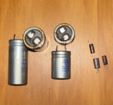
I guess you can see the problem!

faulty caps.png

Large caps - One cap is completely open circuit and the other three are way out of capacitance. The smaller ones also test out of capacitance value. I will replace all the small caps in any case as this will be cheap insurance.

The bridge rectifiers tests OK in diode mode. Would you still recommend I swop these out?

I tested the diodes and they are inconsistent in values, so will replace these. I will also replace the voltage regulators and small transistors as these have worked hard and did get very hot.

The resistors still tests out of spec, so will get new ones.

Next step is looking at the trays of components I have and then onto buying those replacement parts I do not have.

Any recommendations @Family_Dog before I finalise the list and place an order?
 
Your modus operandi sounds good. The bridge rectifier is unlikely to be damaged - you can confirm this with voltage measurements after having replaced the other components. Electrolytics with low values would certainly affect the DC voltage rail negatively.

Re the burnt thumb: As a school kid I had the disgusting habit of bringing the soldering iron tip close to my lips to feel if it was hot... until the time I actually made contact with my lip!


-F_D
 
Those main PSU caps.... As long as the supply voltages are within 10-15% and balanced (sides within a few % of each other) you good. also check for DC ripple on those main filter caps.

For the DC offset, + or - normally does not matter, around 20 is almost always considered to be perfect, less than 80-100mV is still ok, not ideal but ok. Als check the bias, and if you can adjust that. Don't go on a full recap if you considering that. First get the amp stable and working with what is in there or replaced failed or leaky components.

BesteGroetnis
Dankie @Sarel.wagner ek werk maar van 'n kant af.

Will go back to the main transformer and work forwards from there. The issues remains the silly ribbon cables that allow very limited space for work access. These ribbons tend to make you invent new words or remember ones you have long forgotten.
 
Those main PSU caps.... As long as the supply voltages are within 10-15% and balanced (sides within a few % of each other) you good. also check for DC ripple on those main filter caps.
The one is dead ... Will replace both.

What is an acceptable DC ripple value @Sarel.wagner ? I know more or less absolute minimum about amplifiers so this is my learning curve case.
 
That depends :oops: as iy always does. If you can hear hum, its way to much ripple. Remembering that ripple changes with load (Volume) so at low volume, or with the amp idling and no input signal, there should be very close to nothing on the DC side. Check each rail to ground, they shoul be very close to each other.

The style of PSU, regulated or unregulated will also have some bearing on this. As a general stab at this, DC component less than 5% at load and likely less than 0.1% no load. But dont chase your tail on this....

Groetnis
 
Spent last evening to find parts ... not an easy job! The amplifier is more or less 22-24 years old.

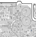
This evening was spent starting at the very beginning of the circuit. The mains transformer. I worked through the schematic and found that the rectifier D121 circuit (yellow) must be supplied with a voltage higher than the 76V it must deliver and the circuit for rectifier D122 (red) with something more than the 46V required.
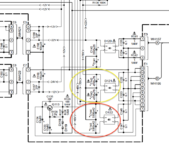
rectifiers voltages.png


It took some time to figure out the correct order of the transformer pins that lead to these two rectifiers. No use looking at the circuit diagram and counting pins. It is not in the same order as indicated on the diagram!

I finally figured it out and measured the voltages between the pins as indicated in the figure below.
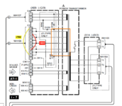

transformer pin voltages.png


It was not even close to the two indicated values. The other pins also did not deliver the correct voltages but not with such a large deviation. I pondered and then pondered some more. The only thing left was that the transformer is faulty or the circuit downstream from the pesky ribbon cables were pulling the output down.

Sigh and sigh and the digging deep for some courage I decided to desolder these once again. Sigh again ...

Alas, no difference. Why would a transformer become faulty? This one looked good and not hot spots were visible. The only thing left was that the transformer either received an incorrect voltage or the output pins I measured on received the wrong voltage.

I took out my big soldering iron and resoldered all the transformer wire connections. Wires onto the pins and pins onto the PCBs.

Connected AC once again and measured. Perfect voltages now! Both 20% more that the values stated. There we are!

A working transformer! PCBs need a clean once I have resoldered the ribbon cables.
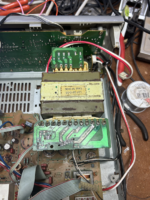
transformer soldered.png

Just shows again that age will oxidise solder thus creating bad joints! Guess I will have to resolder all the joints on the PCBs ...
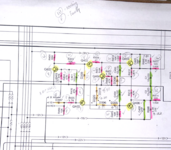
 
Thanks @Family_Dog I am learning a lot! Which is the main aim of this project.

This morning I woke up early and decided to check the bridge rectifiers under voltage supply.

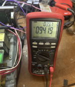
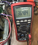
Both the larger ones rated to 200VAC works fine and delivers 94,2 VDC. The smaller one rated to 50VAC was next up for a shave. It works fine as well and gives a steady 36,5 VDC.

I do notice a bit of AC leaking through as can be seen in the smaller top right number. Is this normal?

rectifier voltage 94.png

rectifier voltage 36.png


EDIT: OK, reading some solves the question. This is actually the pseudo AC ripple @Sarel.wagner was talking about. I trust the new capacitors will smooth this out.
 
Last edited:
There will be AC ripple on the DC if the caps are shot or not in circuit when you measure. This is more "pulsating DC" than AC leakage. A good Electrolytic cap will remove this. Any AC ripple on the DC will result in a persistent hum from the speakers.

-F_D
 
There will be AC ripple on the DC if the caps are shot or not in circuit when you measure. This is more "pulsating DC" than AC leakage. A good Electrolytic cap will remove this. Any AC ripple on the DC will result in a persistent hum from the speakers.

-F_D
Thanks so much for explaining @Family_Dog !
 
Man, chasing so many different faults. Under no load situations, that AC component should me less than that.

Solder joints, the mess you up badly. Look closely around high current, high heat or mechnical stress points for dry joints. Groot en sterk vergrootglas and plenty of light.

Sterkete en good luck
Groetnis
 
I am looking at what brand of capacitors to buy for the PS circuit and I see this is an even worse topic than cables!

Then in a brand there are various series numbers. Some forums have quite nice fights about what series in a brand to use. Maybe they are confusing brandy with brand?
 
Back
Top