Welcome to South Africa's Audio Visual community!

Welcome to the home for South African audio and visual equipment owners and enthusiasts. Whether you are an audiophile or a hobbyist, feel welcome to join us in the exciting discussions about amplifiers, turntables, receivers, speakers, projectors, screens, restoration and new projects, product reviews, accessories, classifieds, and so much more!

  • The image upload funtion has been upgraded! Enjoy!

Repair Kenwood KRF-V4080D

Repair and fixing of audio equipment
Man, chasing so many different faults. Under no load situations, that AC component should me less than that.

Solder joints, the mess you up badly. Look closely around high current, high heat or mechnical stress points for dry joints. Groot en sterk vergrootglas and plenty of light.

Sterkete en good luck
Groetnis
Dankie vir die raad @Sarel.wagner

The rectifiers I tested without caps so with decent caps (maybe start a new cat, oops cap, fight thread?) the DC should smooth out nicely.
 
It's been yonks since I bought any caps, I have no idea what is available nowadays. The quality of the caps plays a large part in reliability, for PSU caps I use only 105° rated (if available).

I would suggest browsing RS, Mantech, Mouser and see what is on offer.

@pwatts and @Sarel.wagner should be able to offer suitable types.

-F_D
 
Based on the good advice in this thread I found some good capacitors for the PSU section.

These will be Cornell Dubilier SLP472M100H4P3 for the 4700 μF and the Cornell Dubilier SLPX332M100E7P3 for the 3300 μF smoothing caps.

For the two other smaller voltage power caps I will use Nippon Chemi-Con capacitors as none is currently in stock in the Cornell Dubilier make.

I must say that I am fortunate in that the lead pitch of the old capacitors are the standard 10mm and 7,5mm which makes my life a lot easier.

For the smaller capacitors as found in this diagram I could get Nippon Chemi-Con and Panasonic versions.

Now onto finding the various transistors.
 
Onto transistors ...

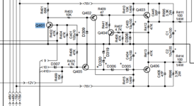
1713125391138.png

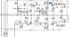
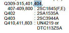
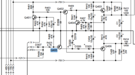
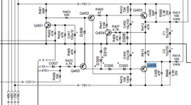
With reference to this diagram let's start with Q401. This is indicated in the parts list as being a 2sc1845.

I am glad I found the site www.el-component.com which gives most all information on a transistor and equivalent replacements as well.

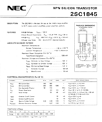
From the datasheet for the 2SC1845 I could pull the characteristics which reads as follows:
1713125780172.png

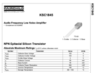
This transistor is not available anymore and the equivalent as per EL-COmponet is the KSC1845. Note however that the leg order of the KSC1845 is reversed to the 2SC1845 when referenced to the flat surface. Something to take note of!

1713126739350.png
 
Onto transistor Q402 ...

1713155286594.png


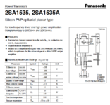
The original one as found on the PCB is the Panasonic 2SA1535A with characteristics as follows:

1713155313950.png

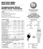
The equivalent as per EL-Componet is the MJE15033 with characteristics as follows:

1713155697434.png

______________________________________

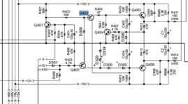
Next transistor for an inspection is Q403.

1713156105195.png


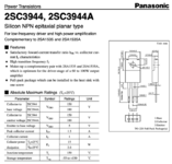
The original one as found on the PCB is the 2SC3944A which is the complement to the 2SA1535A (Q402) with characteristics as follows:

1713156350667.png

The equivalent is the MJE15032 with the characteristics as per the MJE15033 sheet above.


______________________________________

Onto transistor Q404.

Aha this is the same as Q401 !

1713156782977.png

______________________________________


Let's see what we find with transistor Q405.

1713156843955.png


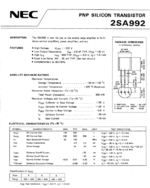
Q405 is a 2SA992 and the characteristics of this transistor reads as follows:

1713157185607.png


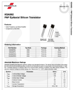
The equivalent as per EL-Componet is the KSA992 with characteristics as follows:

1713157381854.png

Once again the leg order of the KSA992 is reversed to the 2SA992 when referenced to the flat surface!
 

Attachments

  • 1713158322389.png
    1713158322389.png
    83.6 KB · Views: 3
The last transistor proves to be a bit of an issue.

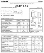
Transistor Q406, as per the service manual it is a 2SB1640.


1713159212484.png


The characteristics are:

1713158599716.png

I simply cannot find this transistor or an equivalent in South Africa. Maybe @kolakidd or @ludo or @Family_Dog or someone can help with advice?
 
Herman, do all these transistors need replacing? Regarding the 2SB1640, this appears to be a stumbling block, apparently it was discontinued some years ago. Pretty sure you could use a more modern equivalent but one of the other guys will have to provide some meaningful substitutes here, I would hesitate to offer a suggestion for a replacement.


-F_D
 
@Family_Dog they all ran hot (as you ID'd as well) so it could be an issue hence I am trying to ID these with the point of view that I might need to replace them. I am planning to install the old ones and see what is what, but on the other side of the coin to ship cheap transistors at a later stage is not money worth spending on shipping fees.

The SA conundrum of buying things online ...
 
Running hot could have been caused by incorrect biasing due to incorrect DC voltages because of resistors or caps going yucky. Hope you come right with it, it's worthwhile getting the old girl on the go again. Replace the heatsink paste as well.

-F_D
 
What I don't get, is that 2SB1640 (listed 4 times in the manual as Q406) is a -60V device regulating a -76V line. On the positive (+76V) side there is 2SC3944 (Q403) which is a 150V device. Why did they not use it's natural complement (2SA1535) on the negative side for Q406?

Unless I'm missing something obvious here (and that would not be unusual...) 2SB1640 should just fail.

Is it actually a 2SB1640 on the board?

The MJE150xx On Semi devices (PNPs) should work fine for Q406, if it needs replacement. Neither is a very fast type.

For replacing an actual 2SB1640 I would think even the humble BD244C will do just fine.
 
That is what I do not understand either. My first thought was that Q406 would be a 2SA1535 and then to my amazement I looked up Q406 as the 2SB1640.

Yes, the 2SB1640 is what I found on the PCB.
 
As I see it when Q403 & Q406 are on, the STK413 chip gets +46/-46V supplies for its voltage amplifying stages. When Q403 & Q406 are off, the STK chip gets +76/-76V. The STK chip switches the power lines for its high current output stage internally.

Q403 & Q406 are switched off when appropriate by Q402, via Q401. The 4 zeners (D305/D306/D319/D320) set the 46V reference. Q404 puts the brakes on Q403 when the junction of R412 & R413 goes to far above Gnd, so the +46V line tracks the -46V line.

Q405 is manipulated by the output relay switch (Q410) and by the microprocessor via D307 (3.9V Zener).

Q401 is manipulated by the same uProc. I suppose it keeps an eye on signal dynamics and knows when 76V lines are needed.

I suspect that all works OK if the amp did play.

Seat of my pants says that either there is oscillation in the power amps, or there is a dry joint somewhere, most likely somewhere where there is significant current flow. But it could even be the bypass caps around the uProc that have gone dry.

What I also notice is that there is no bypassing on pin 12 & 13 on the STK chips. So the voltage amplifier stages will be talking to each other. At 46V and 76V they are all driven from 100 Ohm (R411 & R414) The STK datasheet recommends 100uF from each of those pins (pin 12&13) to Gnd.

Now whether the present arrangement without bypass caps will cause oscillation I can't say. It must have worked before. But it might be instructive to put a scope on those speaker outputs to see what's there. Oscillation might trip the over-current protection, the more so if C336 has gone the way of all things. If it is not in very good shape any low freq might also cause a trip of the protection, and it can be Temperature related. Its neighbour C335 checks symmetry of the supply lines and may also be a culprit though it seems less likely. Dry joints in the supplies will trip this circuit. Both these protection systems talk to the uProc (PROT1 & PROT2)

I have learnt that most of the time it helps to be a bad loser. Blood from a stone works for me most days. But if that amp was mine I'd have kicked it down the stairs by now. Modern things are needlessly complicated. Much respect to you for still trying (y)
 
@ludo, I have wracked my brains and cannot see why Q406 is a 2SB1640.

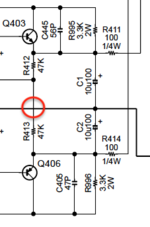
I did notice that my brain wants to read a connection to the ground track which actually does not exist. Note the absence of the connecting dot as indicated below.


not connected.png

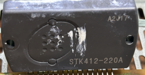
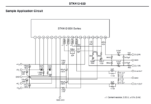
This amp has an IC STK412-220A installed

ic chip.png


I also looked at the IC diagram and the typical circuit for the IC STK412-020 has a voltage of more than 60V on its pin 12 which Q406 supplies.

1713214095586.png

EDIT: Your replied while I was posting this. Let me first read what you have said. Thanks!!
 

Attachments

  • 1713213229336.png
    1713213229336.png
    51.7 KB · Views: 3
Last edited:
Thanks for your detailed explanation @ludo. Much appreciated!

I have not tested the Zener diodes in the correct way. I really have no idea what the actual correct way is to test these. With a DC supply circuit or with the diode function on the multimeter. I need some guidance here please.

I am past kicking stuff ... you just hurt your big toe and then you need to live with that pain as well! This exercise is for me to learn more about amplifiers and the repair/restoration thereof. Must say I have learned so much the past few days!
 
One other thing I simply cannot find is a way to set the DC bias for each channel. There are no variable resistors I can find.
 
Being short of a curve tracer, I check with with the DMM. As a rule of thumb I notice something like 1N4148 or 1N4007 has a forward voltage drop around 450-600mV but Zeners tend to be a bit higher at say 650-750mV.

When measuring in-circuit one has to consider what is connected around the diode of course. Then you are measuring the forward drop at that point in the whole connected circuit, not just the diode.

If you go to the trouble of rigging up a current source for a Zener diode (usually a voltage source and a current limiting resistor) you will probably notice that the tolerance is not so great.


The STK chip contains the entire power amp circuit. Bias is set internally during manufacture. To check if the output stage bias is within reason you can measure the voltage drop across the 0.22 Ohm resistors that are connected to pins 8&9 and to pin 10&11. At a guess you will see around 4mV-22mV across each 0.22 Ohm resistor. Finding the sweet spot requires a spectrum analyser or an insight that most of us are probably not capable of. I usually check the bias without a load connected. If there is significant offset voltage on the amplifier output you will notice a proportional difference between the positive and negative sides of the output stage idling current.

I have a bad example of a Mos amp here with -380mV offset on the output. In an 8 Ohm load that draws 47.5mA through the negative half of the output stage. So the output bias is always going to be lopsided. Works OK though.
 
Cross-eyed to say the least!

All solder joints redone!

resolder 1.png


And cleaned with PCB cleaner. Looks almost new ...

resolder and cleaned.png

Some of the junctions were so oxidised that I had to remove all the solder and clean the component wire and resolder.

I stopped counting at 10 dry joints. Would say at least 50% of the joints were dry joints. Some were under tension and when I applied the heat you could hear the ping as the component clicked into place.

When I can see again I will solder the transistors and the bridge rectifiers back into their sockets.

The removed Zener diodes test wonky with the DMM. You can test and test again and get different values simply by holding the Zener glass section between my finger tips. Will replace all of these as well as the other normal diodes found in the heated section.

Onto searching for the Zeners online!
 
The evening was spent retesting each removed component and then soldering the good functioning ones back in.

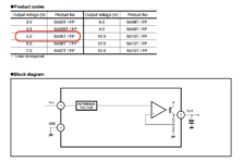
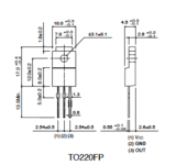
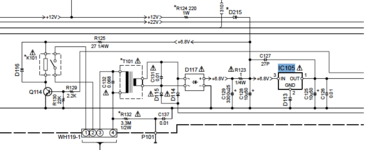
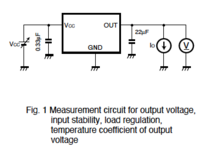
I found another problem! IC105 (a BA05T in a TO220FP package) which is a voltage regulator, is suppose to give a steady 5 VDC out as per the specification sheet.

ba05T.png

If I look at the pins of the BA05T component it shown that pin 1 is on the left hand side:

1713386398077.png


If I look at the circuit diagram for the amplifier it shows that pin 1 is OUT. This is not matching with the specification sheet. See below.


1713385852954.png


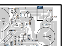
If I look at the component diagram and the connections of IC105 to C127 and C125 and C128, then C128 is on the input side and C125 on the output side.

1713387692245.png


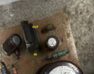
Comparing this to the way the IC was installed with the recess to the right hand side, it must mean that leg 1 is connected to C128 and leg 3 connected to C125.

IC105 as installed.png

This means that the circuit diagram is incorrect and leg 1 and 3 numbering are switched!

I tested the IC as per this diagram and it fails miserably in keeping voltage at 5V.


1713388162972.png


Will replace it as the output voltage and ripple removal function of this IC looks quite important.
 
Last edited:
Your diagnosis looks correct. Finding a BAT05 is not going to be so easy though.

You can try LM1117-5.0 but note that it has a different pinout again and will require some bending of the pins.

The readily available LM7805 has the same pinout as BAT05 but will not work. It has to be a low-dropout regulator like LM1117 seeing as input voltage is only 6.8V.
 
That 5.3V output from the regulator goes all over the place. Can cause no end of trouble if it is flakey
 
Back
Top